Blog

AH-64D CPG dash for desktop use – build

So it begins, into the rabbit hole we go….

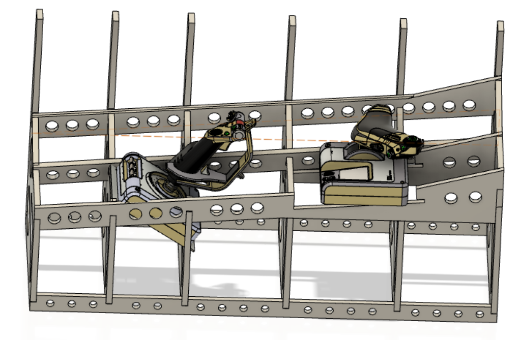
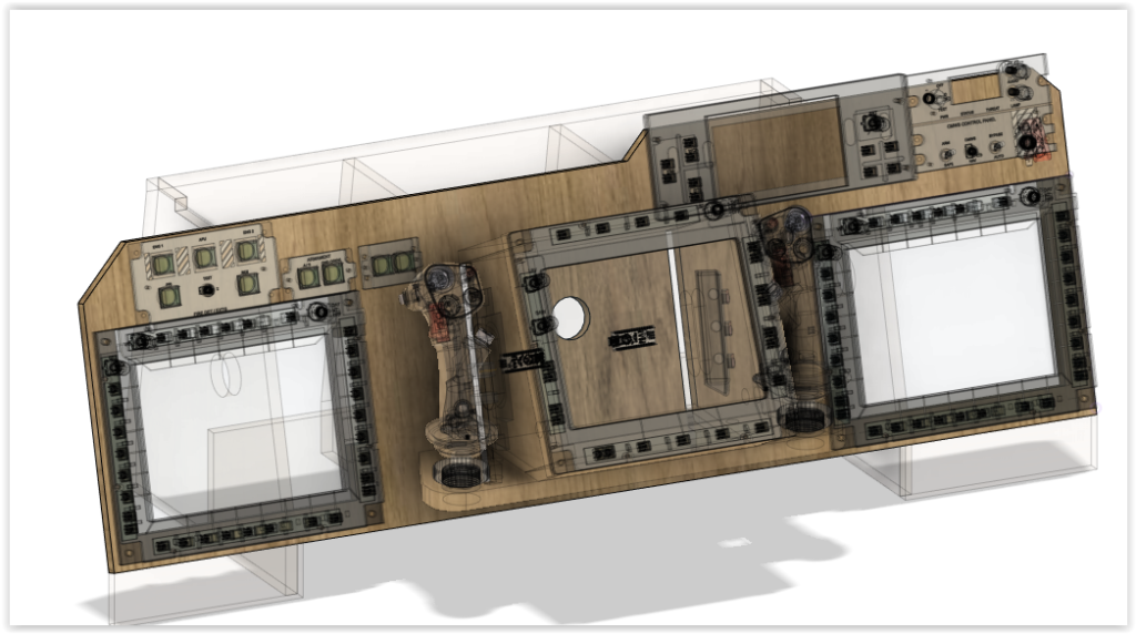
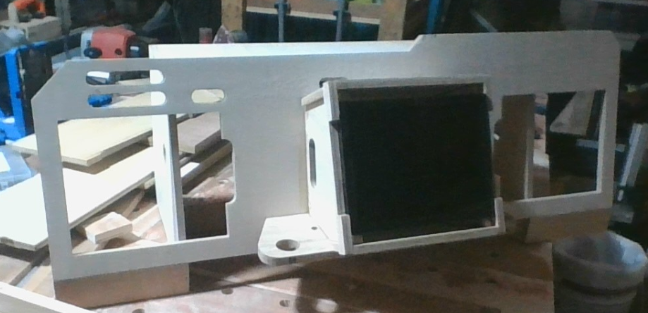
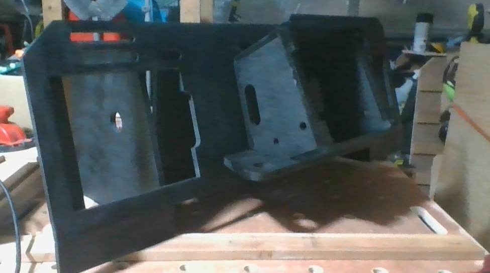
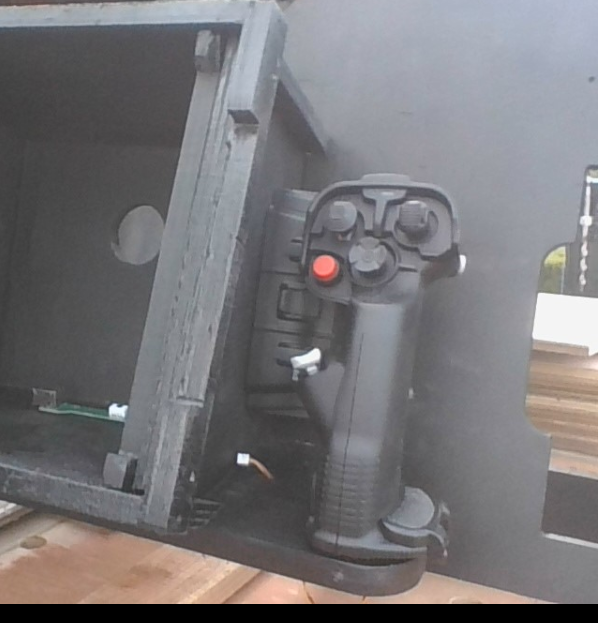
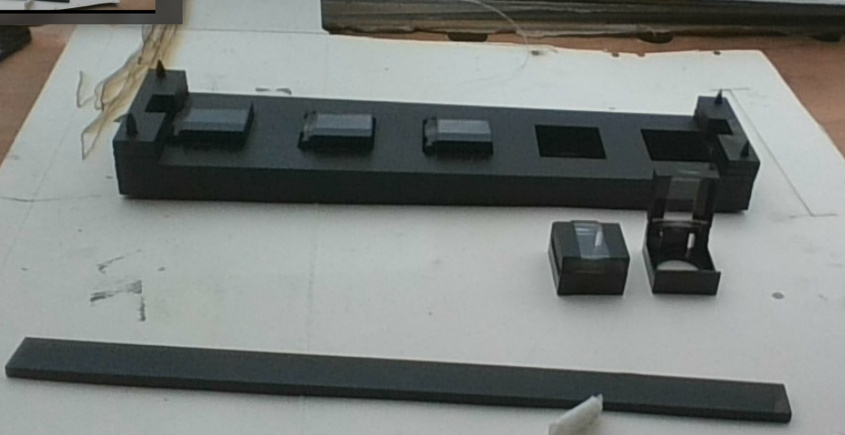
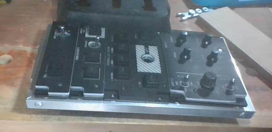
The thing about scale is… it looks good on paper, but then once you’ve built it…. it’s too late, so before i got carried away i wanted to ensure that the primary tool was going to be comfortable, this was the TEDAC/TADS setup, so the first thing i did was cut the grip moutning bracket & sat the 2 grips & the intended TADS screen to get a feel for it.

TEDAC grips & TADS display placement verification

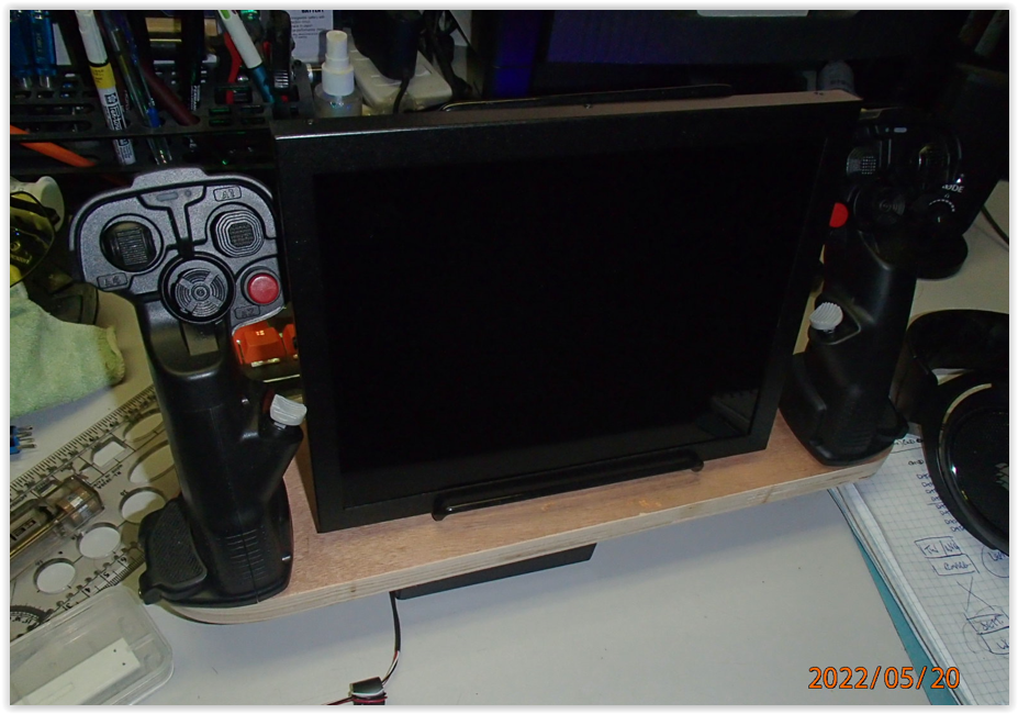
Glad I did, I ended up adding a little to the dimensions just for ergonomics.

Once happy with the mount dimensions, i had to tweek the remainder of the pieces to reflect the slight changes, then i could begin cutting everything out

CNC for the win

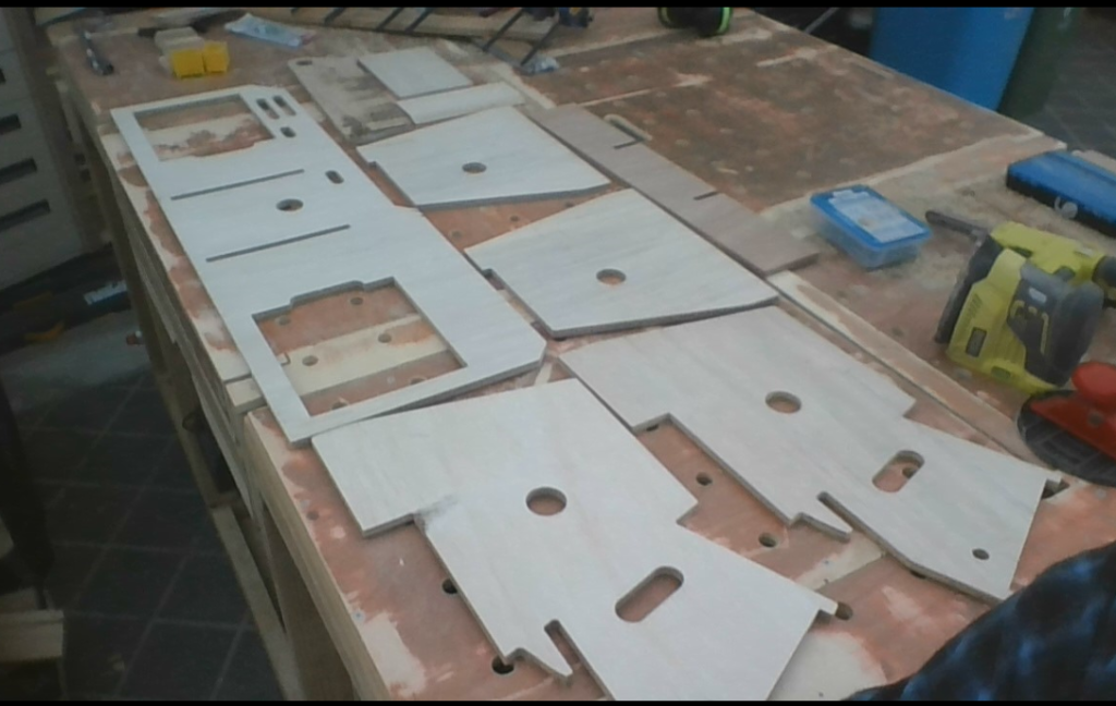
sadly regardless of which mill bit I use, there is always lots of sanding still required…. sanding….. sanding……sanding.

cleaned up & initial fit assembly

It is always nice to see a project take shape.

Grip & base placement

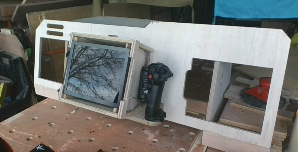
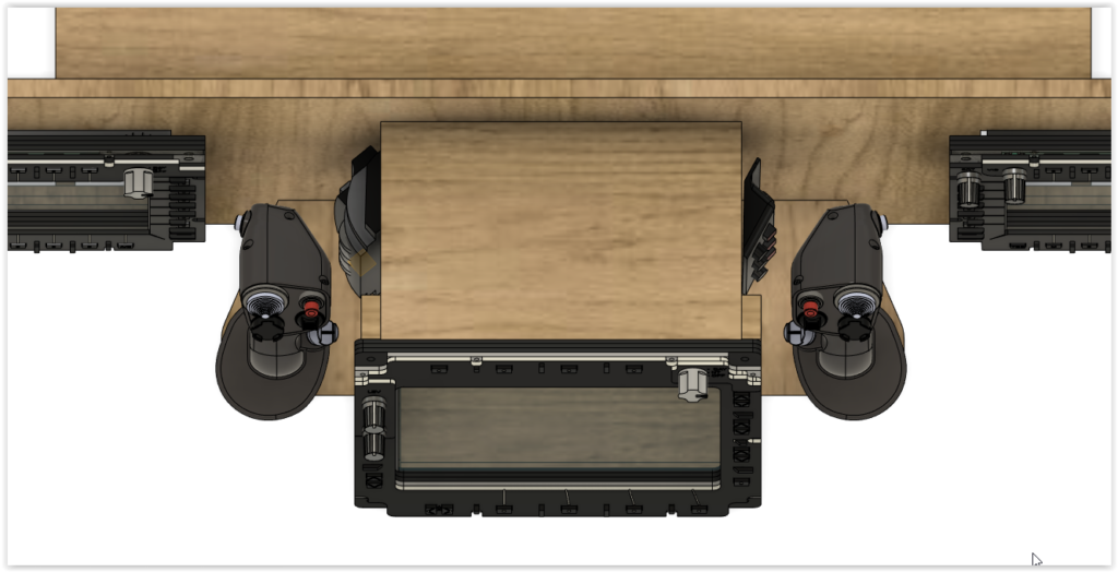
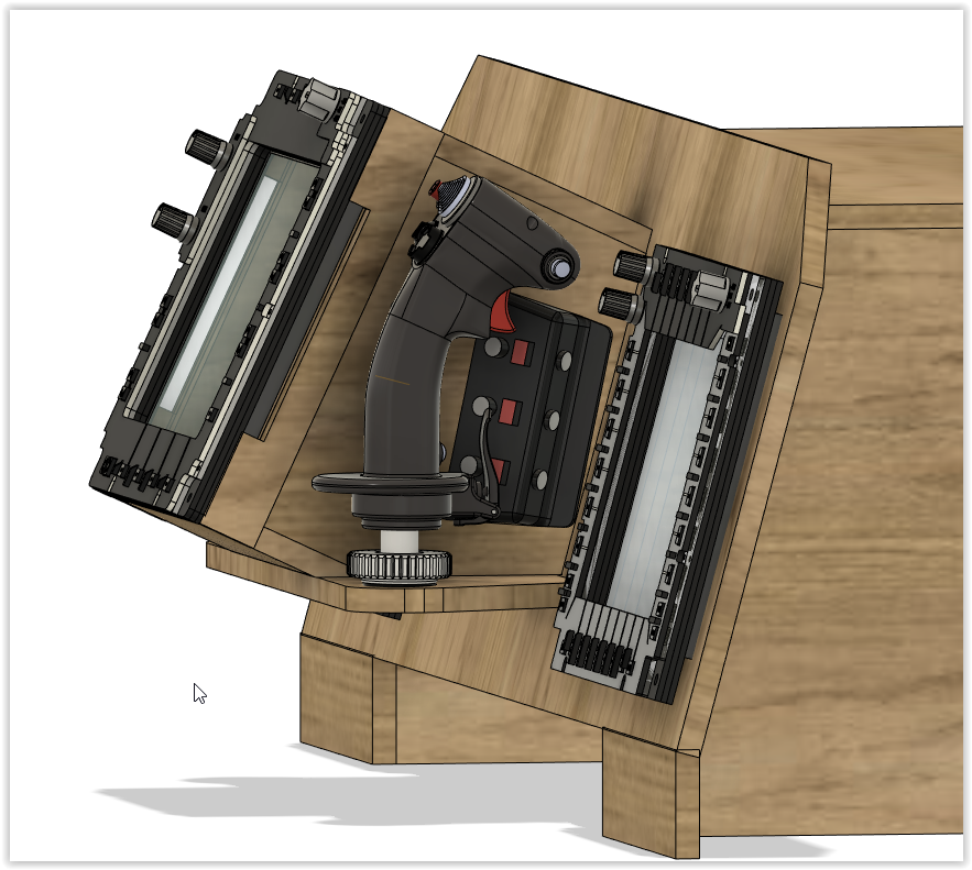
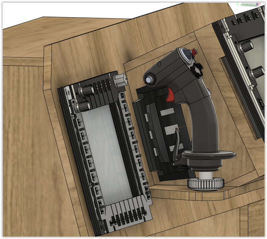
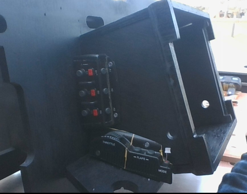
Now i could investigate how well the base of each stick would sit & set the perfect height so that it was easily reachable by a reaching out with the fingertips whilst resting on the TEDAC grips.

Wiring confirmation

At the same time i needed to make sure the factory supplied cable lengths were suffice to thread through the TADS mount to get back to the PCBs from each base that were now housed in behind the TADS screen. fortunately i only had to lengthen one of the wire looms, I probably could have gotten away with it, but there is always something that needs maintenance, & not being able to easily remove a component or at least set it aside whilst still connected is a pain, always try to give yourself a bit of slack. You’ll be grateful for it one day.

undercoat

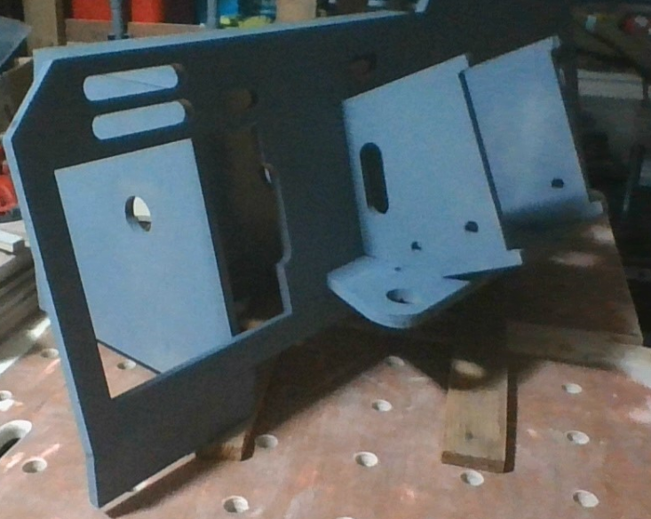
I cannot explain how much I hate painting, i thik it’s mutual as I always seem to end up with more up my arm & in my hair than i do on the brush. So spray cans it is…. I must admit though, a simply lick of paint makes all the difference.

basic black

First top coat, to give it that intended end result.

Now for the fun stuff, mounting up & connecting all the components

Base mount

Wood screws placed in strategically located imporovised mounting holes so as not to hit anything vital….

I scratched it already!

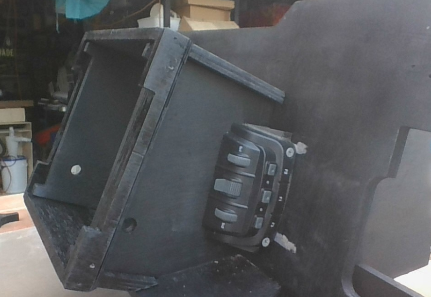
placement of this base required longer screws at the rear of the base section, having the powerdrill that close resulted in marking the panel…. not to worry, more touching up to come.

mounting LH grip

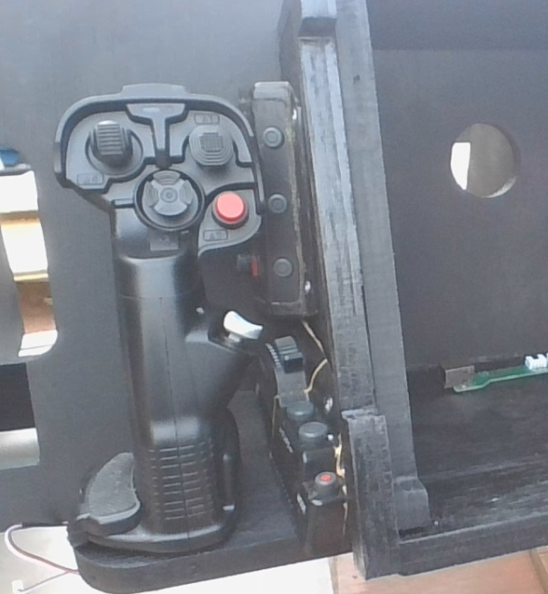
Mounting each grip & threading the wiring through the access holes back to the PCs is a bit of a catch 22, as some of the grip wiring runs under the mount, then back up & behind the base sections & into the TADS mount to the PCB, couldn’t make it too easy.

mounting RH grip

Reaching around the grip & trying to lift a loosely secure base section to thread the wire through is problematic enough without short wiring & fat fingers….

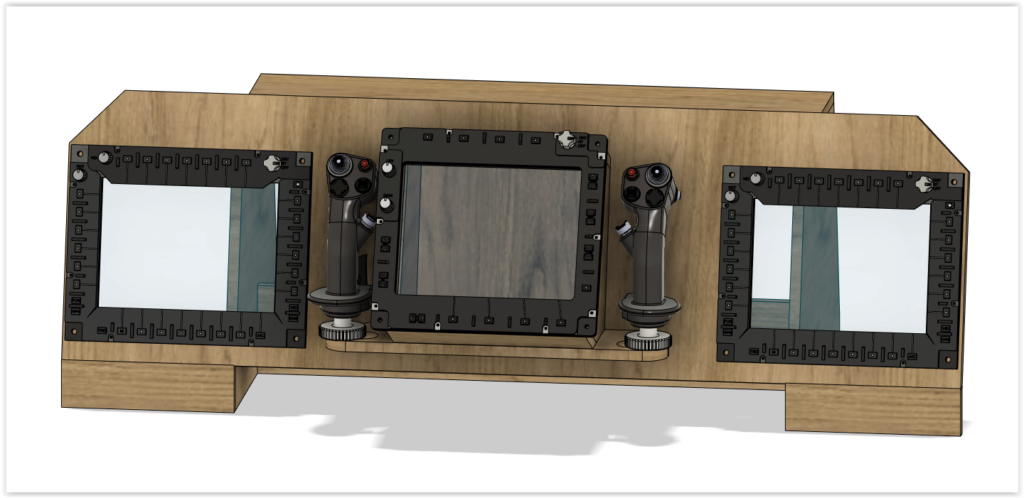
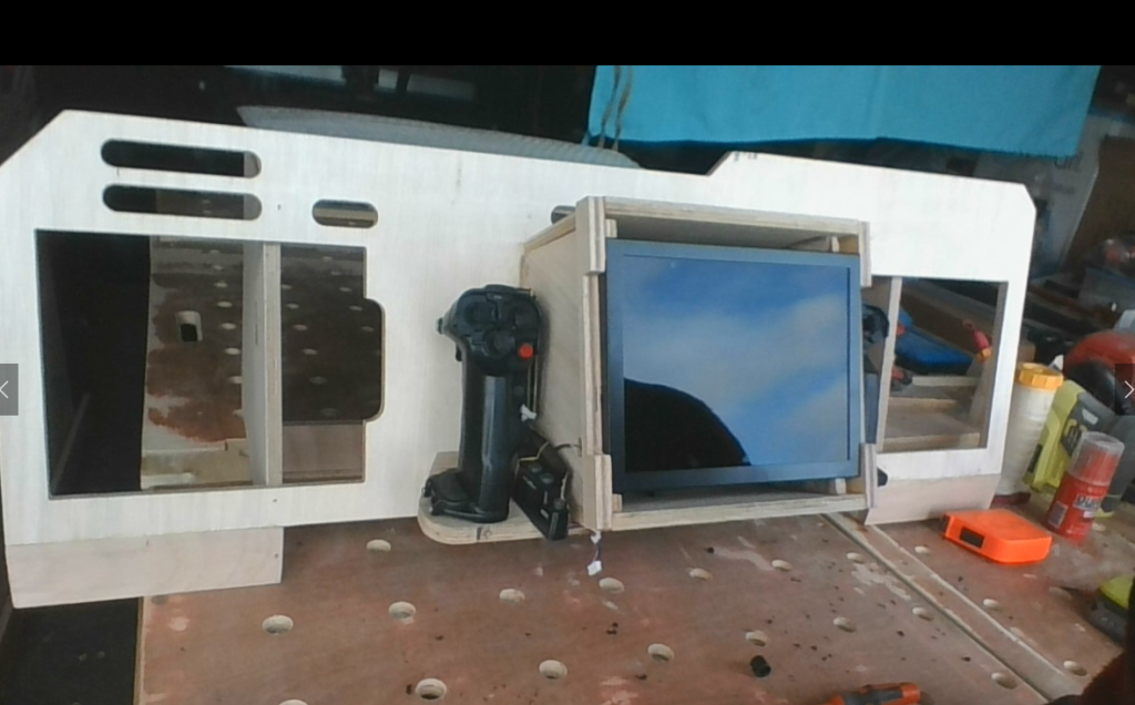
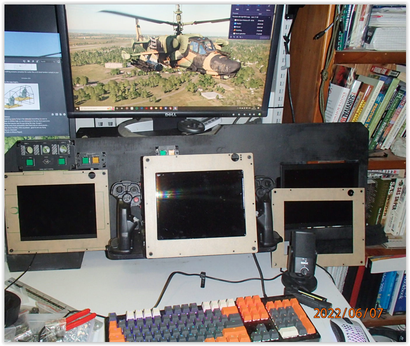
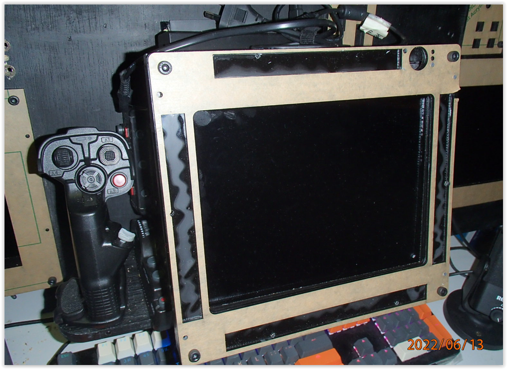
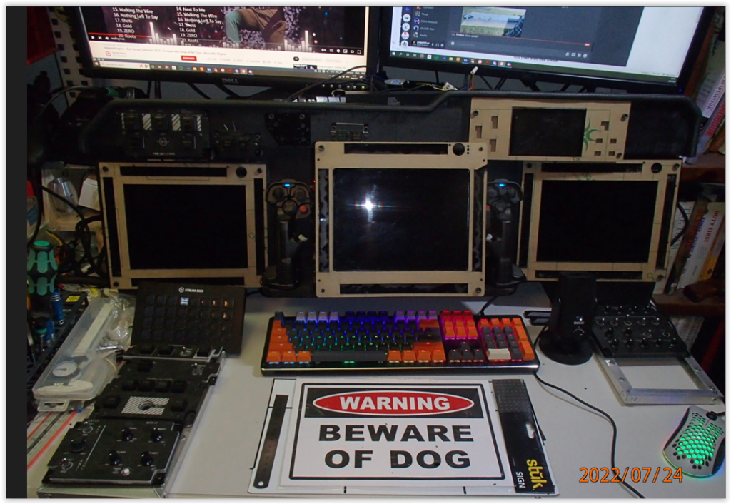
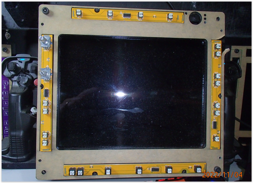
Once the grips were in place I was ready to mount the displays & conduct the first test.

initial test

These displays are very clear & just beautiful. Config is easy, no real problems encountered. They will not run on USB power though, so you might need a 12V power supply, if you have an old PC power supply, cannabilise it to run these panels & all the back lighting in your pit…

Time to start fabricating the MFD panel layers to hold the displays in place

panel fabrication, first batch (base layers)

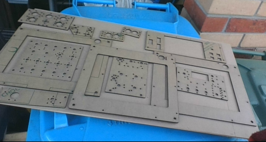
All my panel production is pretty much the same method as used by the Warthog project (why reinvent the wheel). It works as advertised.

I got carried away

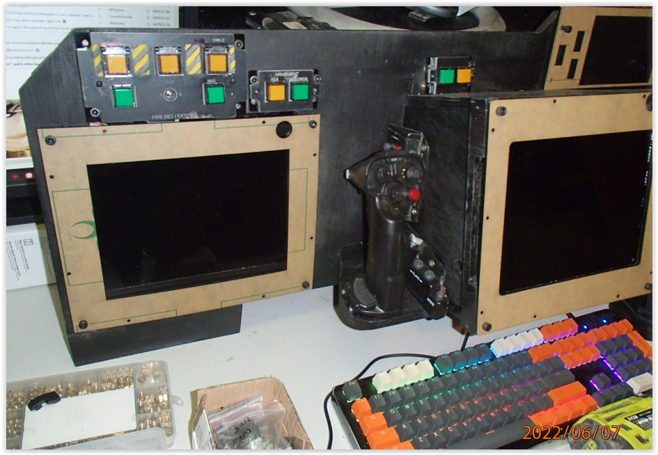
I was only supposed to be making the MFD base layers to hold the displays in, but instead i ended up with full sets for the Fire Extinguisher, Master ARM & Master Caution panels…..

thats more like it

Now back to our regular programming…. .that’s what I was supposed to be doing.

threaded inserts

Nothing really noticable changed here, other than the giveaway of the pack of threaded inserts in the bottom corner. I drilled & placed inserts for the panels to mount into so that they wouldn’t fall out & get damaged.

EUFD & CMWS

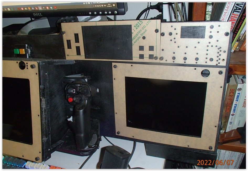
More thread insert placement, this time for the EUFD, I included the CMWS, but I don’t think it will allow me to acti0n these inputs (even with a panel with switches mapped) from the CPG station. I have yet to test this, but I had made the panel so I thought I’d mount it anyway, just in case.

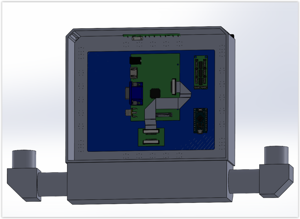
In preparation for the LED back lighting of all the panels, I need to determine the resistors required for each LED string. the small board to the right is a decade board, which allows you to create a ‘custom’ resisitor based on your circuit requirements if you don’t have a specific resistor

LED string Resisitor calculations

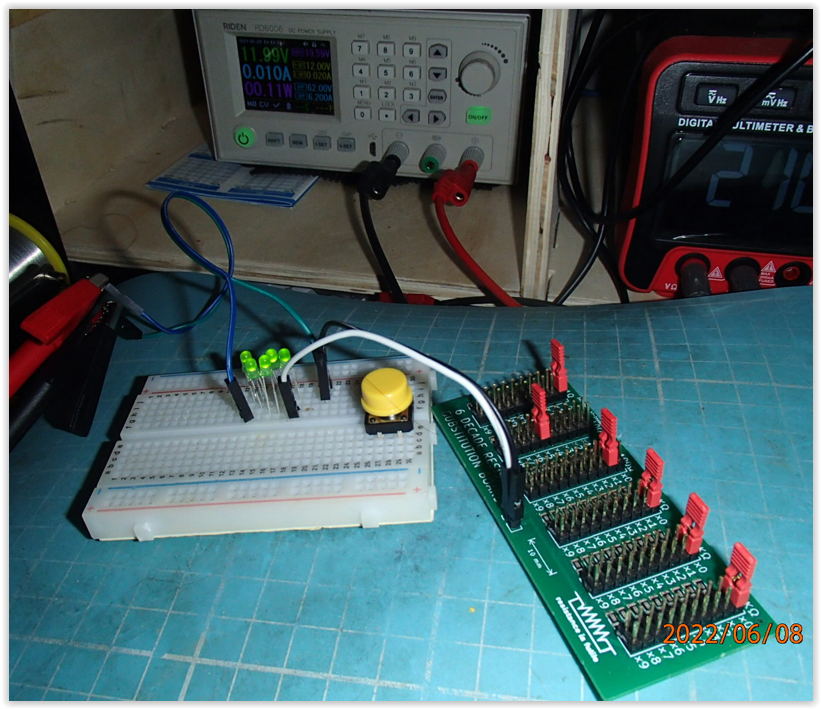
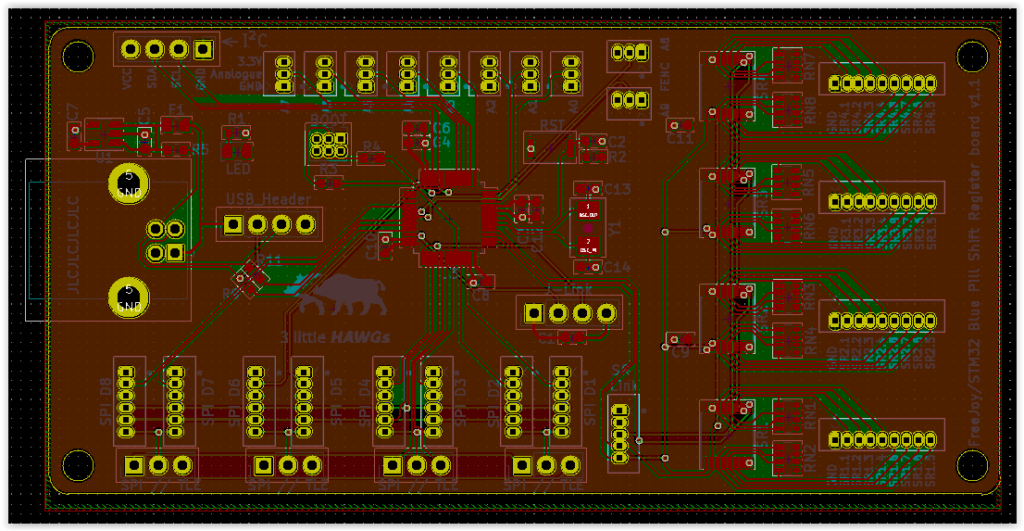
My colleague designed & had this board fabricated as part of his learning curve of using KiCAD, submitting a board for prototyping, including fabrication, so a bill of materials as well as a pick & place file was required. All new ground for us & he did a great job using this small/handy project to test out this process.
Very clever indeed

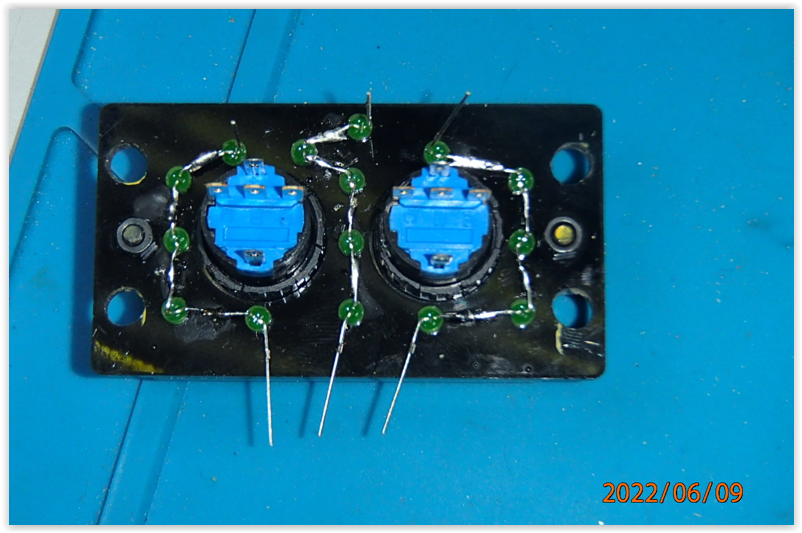
Due to the number of backlights required & the sequencing of max 4 LEDs per string, I also had to plan out optimal string patterns for each panel

LED string planning per panel

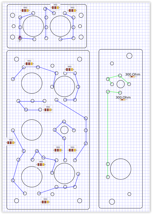
This diagram was when I was assuming i could get up to 5 LEDs in a string, until I realised the Captain Obvious that this wasn’t achievable…it’s hard to find good help

MFD PCB layer

Added an additional layer to the MFDs & TEDAC panels showing the location of the custom PCB strips that will provide the button mounts for each panel

early revision of the TEDAC PCB strip design

each PCB strip is slightly unique unfortunately, so I had to make a set of all 4, with each button, as well as screw holes to accommodate the layer construction.

early revision TEDAC PCB design

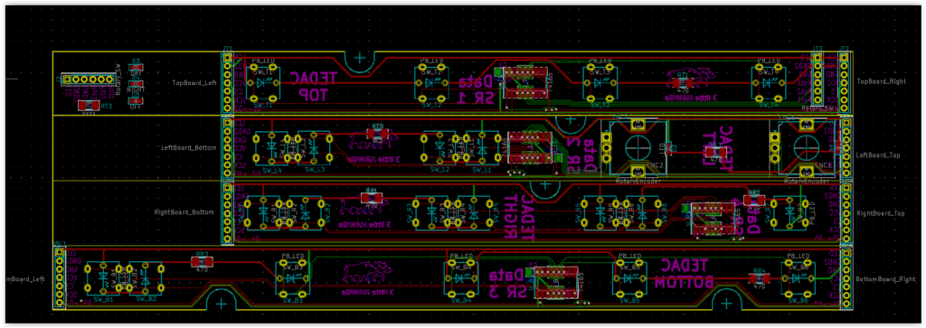
Each PCB strip has a localised Shift register, so that regardless of the number of buttons, there will only be 5 wires running between each of the strips & then back to the microcontroller (FreeJoy) board.

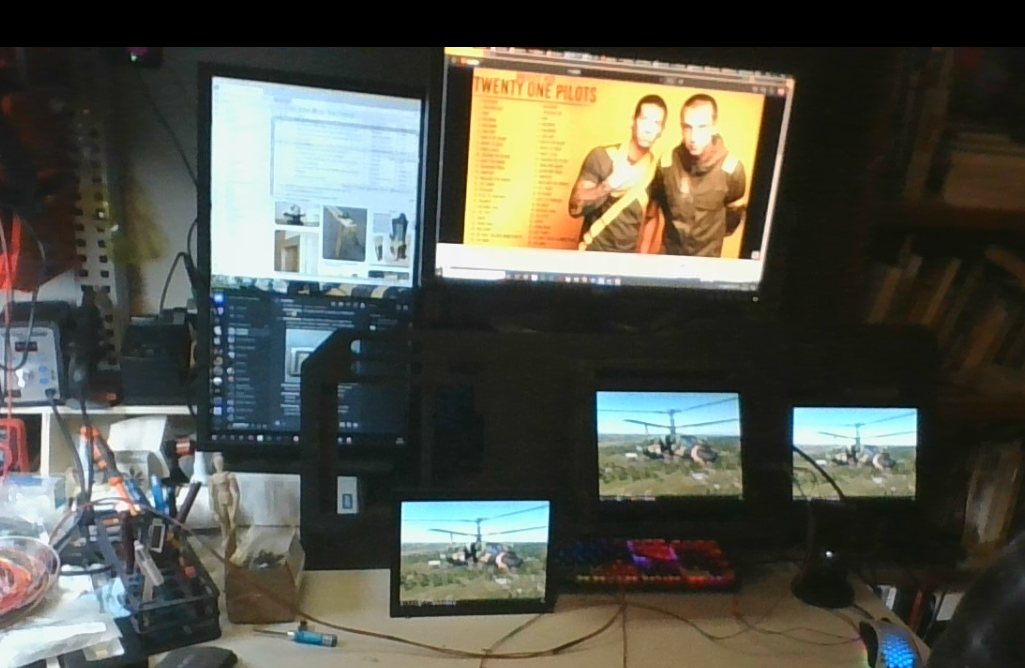
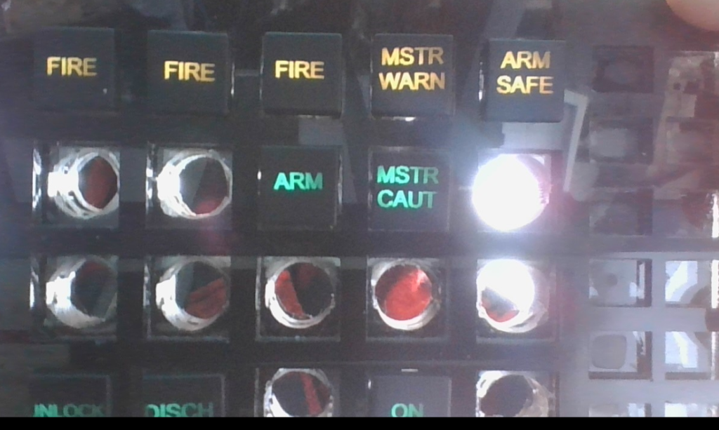
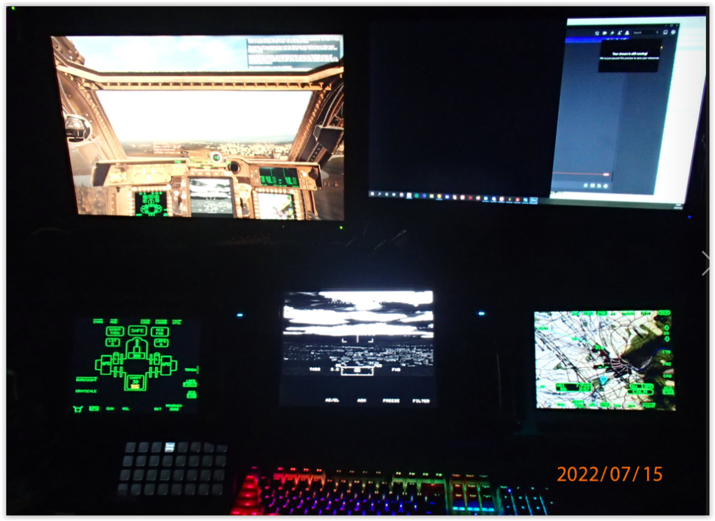
Now to try & get some screen output happening

TADS output – attempt #1

Initially I was only able to get the 2x MFDs working using Helios, despite several attempts to get the TADS output, I wasn’t able to achieve this, but we saw on the Flight Panels fork that the TADs was coming in the next realease, so i busied myself with other things to keep me occupied.

MFD brightness sorted

I was a little concerned with how dim the MFDs were, but with a little tinkering inside the game I realised my faux pas & all was well.

To confirm there was nothing wrong with the centre screen & that Helios was otherwise unaffected I tested out the F-18

I am ashamed

I know, a filthy fixed-wing, but it had to be done to validate the otherwise working config.

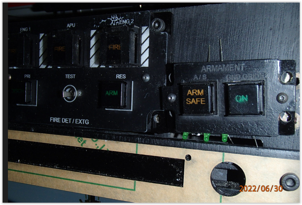
Onto painting the switch caps

LED push button switch

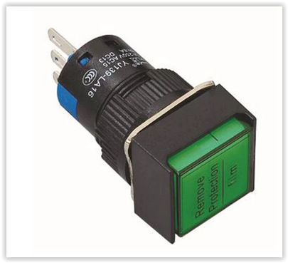
The switch cap can be easily removed from the switch by gently pulling it straight out, take care to not the orientation of the small tabs at the end of the switch cap when orientating them to place them back into the switch

Button cap painting jig

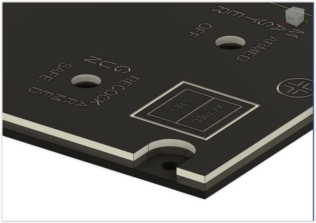
I made a multilayer jig to spray the push button switches with a flat black paint, then once dried I could flip the jig over & placed them in the recessed side, to laser etch each button label. The middle layer of this jig has slots on the sides to ensure the switch cap can only be orientated up or down, but cannot be placed in at 90 degrees (Left or Right), otherwise laser etching of labels will be… cock-eyed

Holding the jig up to the sun was proof or back lighting

switch cap painting jig

I made an additional jig for painting the switch cap covers (APU & Fire Extinguishers) matte black but leaving a clear stripe down the centre.
Worked a treat.

larger panels

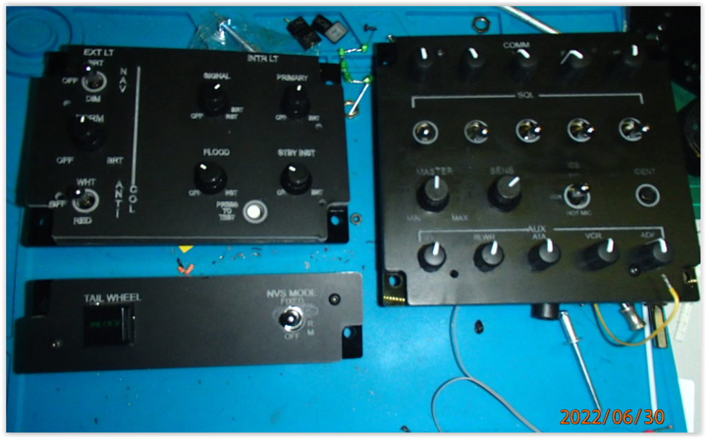
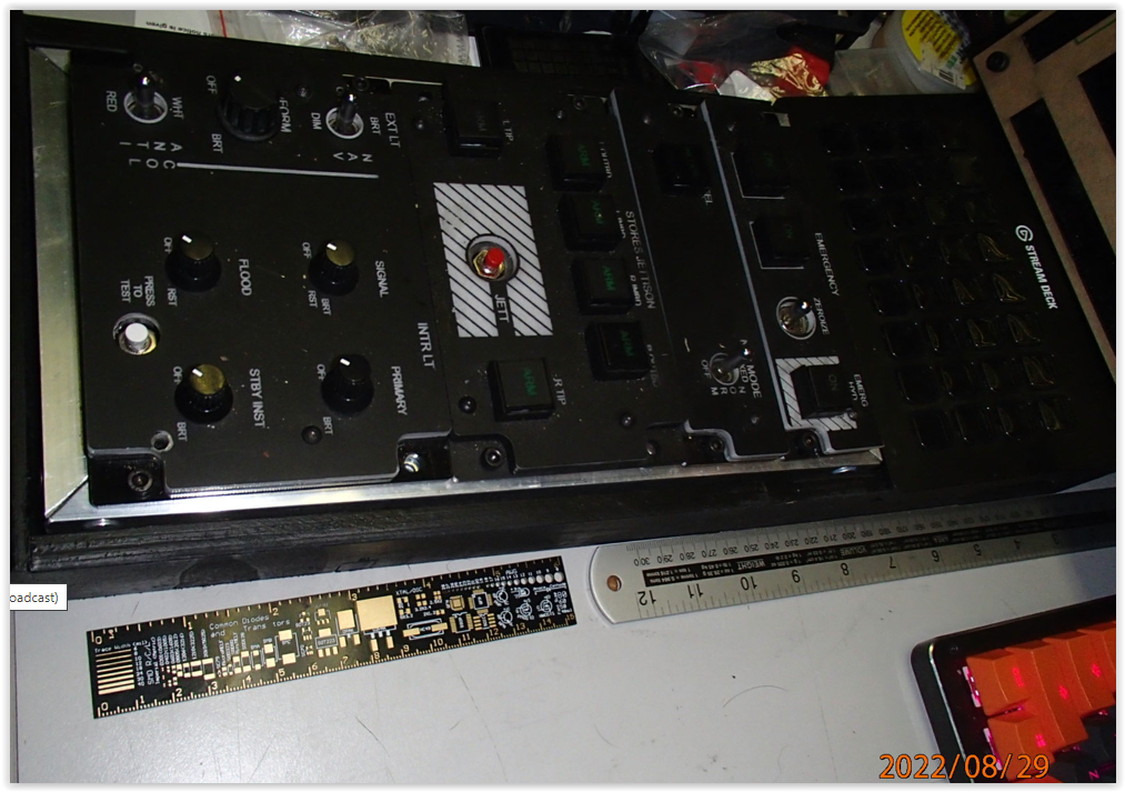
I began constructing more of the larger panels, the light panel took me a could of goes, the first time I laser etched the incorrect label set on it….. oops.

As per the Warthog Projects assembly, each of the panels is a tri-layer fabrication;

  • base layer solid black (to prevent light bleed & mount point for LED)
  • mid layer transparent ( to diffuse light, also has hole for mounting LED)
  • top layer translucent white, with painted surface ( to block light where not required but allow light diffusion to laser etched labels)

It was at this point after assembling some of the panels & prior to putting the switches in place, I decided to give each top layer a spray with a clear acrylic to protect the laser etching of the black paint layer, this however proved problematic.

paint issues

As can be seen above the clear lifted the black paint from the top surface.

So i had to dismantle these panels, then sand the surface paint off, reapply the black paint, allow to dry, re-etch, then reapply the clear acrylic. Still getting mixed results in some cases. So i ended up recutting the top layer of some of the panels & repainting, re-etching, etc. SNAFU

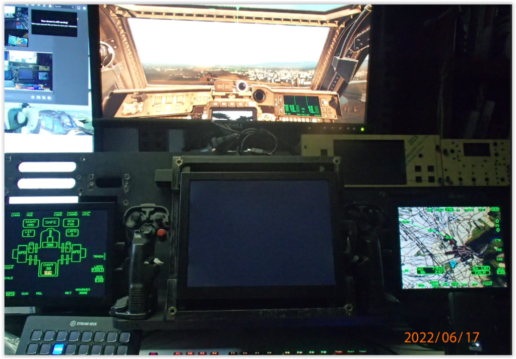
Helios updated & I could finally get the TADS output I so sorely desired, starting to really get the itch now. Cannot wait to get my MFD buttons working also

TADS output

I took this opportunity to also map the controls for the TEDAC grips so that I could tinker a little bit in DCS.

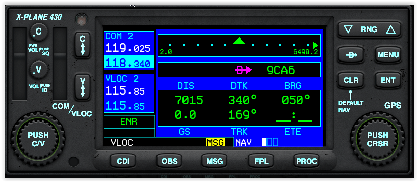
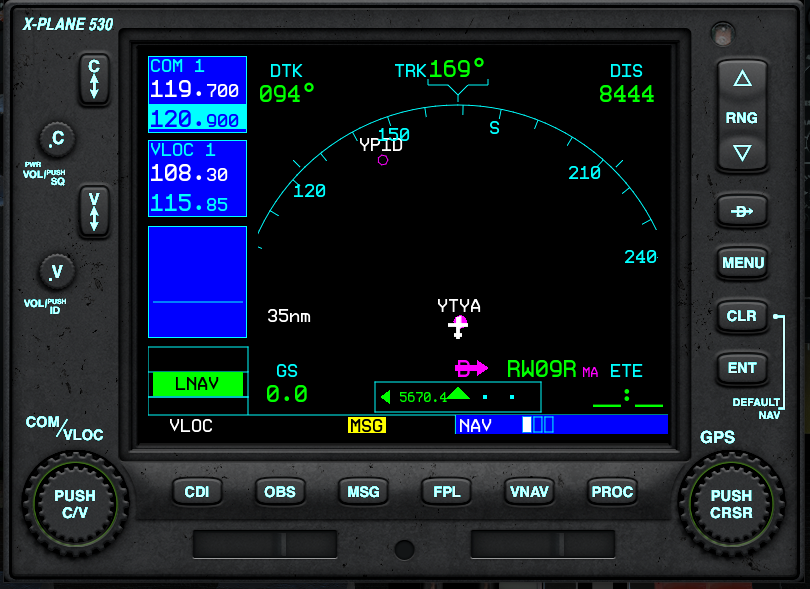
Enough distractions, on with the build, I finally got my next screen delivered & configured it up to serve as the EUFD, gave it a test/base screen to look like a running EUFD so I could verify font size & spacing.

Ran up DCS with DCS-BIOS also running & confirmed all the output displayed & worked as expected. Eureka

working EUFD – live output

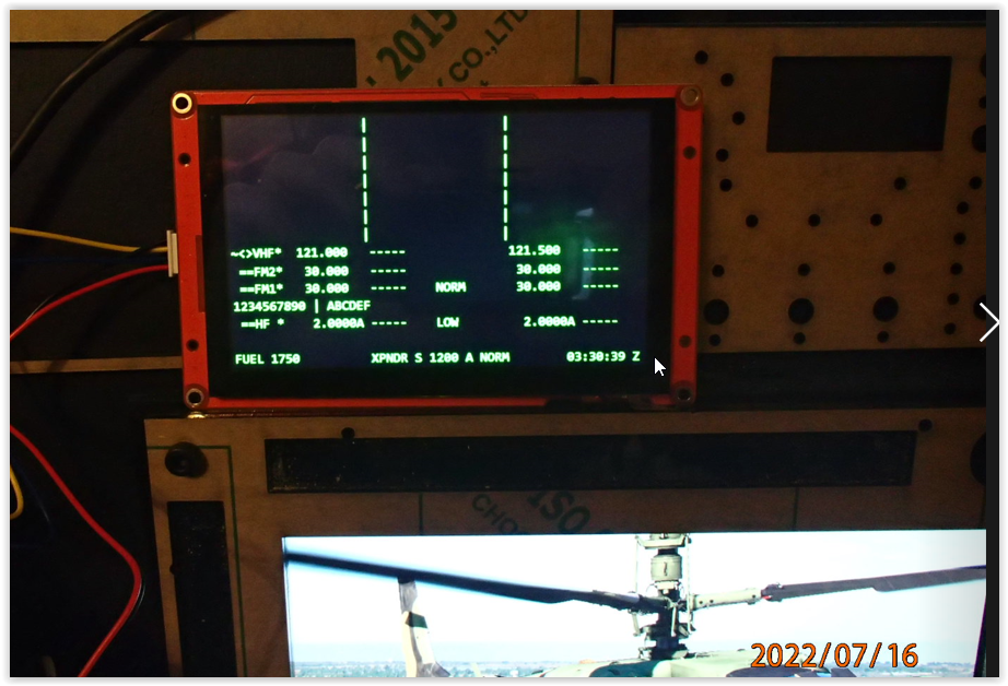
Must admit, this was a nice little goal post to get past. The panels are cut for the EUFD, but I am also designing some small custom PCBs to mount the switches on, which are in the queue, but behind the TEDAC/MFD custom PCB strips

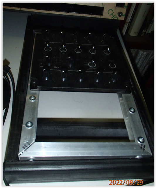
As I continue to fabricate more of the panels for the side consoles, they are getting knocked about a bit as I move one project pile aside to work on another, so I decided to make the mounting frames for them to give them something to sit in & hopefully protect them from any damage.

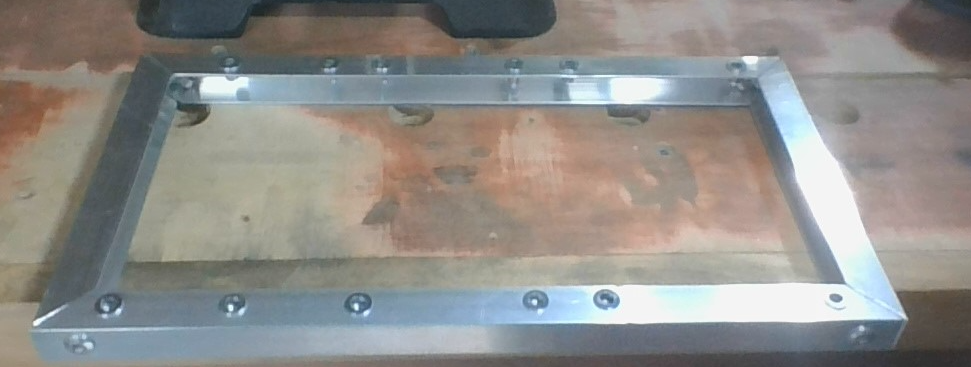
Frames are simple aluminium 15mm C channel, available at Bunnings, in order to fabricate these & not cock up any measurements, I laser cut cardboard templates of each panels base layer along with a pinhole marker for the centre of the mounting holes.

I sticky taped these together then measured the lengths for the side pieces & confirmed the width dimension for top & bottom sections. Cut them, marked drilled holes for small L brackets, then pop rivetted the L brackets ensuring that the frame retained as close to square as possible.

I then took the sticky-taped cardboard panel set, placed them central on the frame & taped them down so they wouldn’t move.

I placed the aluminium frames in a small square jig using my parf system on my benchtop to keep the frame as square as possible. At this scale a few mm isn’t going to matter much, but you know…. OCD

I used a centre hole punch to mark the aluminium frame, then removed the cardboard templates.

Using my drill press I the pre-drilled each hole with a pilot drill to get best result of centre, then changed up to a 6mm drill to bore the holes for the riv-nuts.

Note: Aluminium Riv-Nets are not the most robust things so you need to take care when putting them in to not tear the thread out of them, which renders them entirely useless…. don’t ask me how I know

console panel placement

Once the riv-nuts were inserted, the panels for each side console could them be put in place & secure with M4 hex cap head screws.

At the same time i did the aluminium frames, I also fabricated the top dash protrusion, gave it a lick of paint & put all the threaded inserts in place.

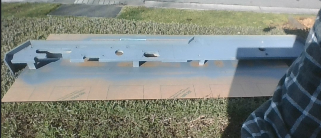
Once the undercoat dried I gave it a coat of black & ran a rubber U -trim along the forward edge to give it that finished look. Came up looking the goods.

upper dash & side console frame assemblies

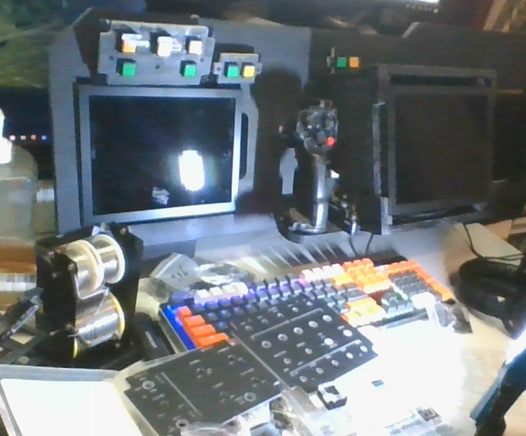
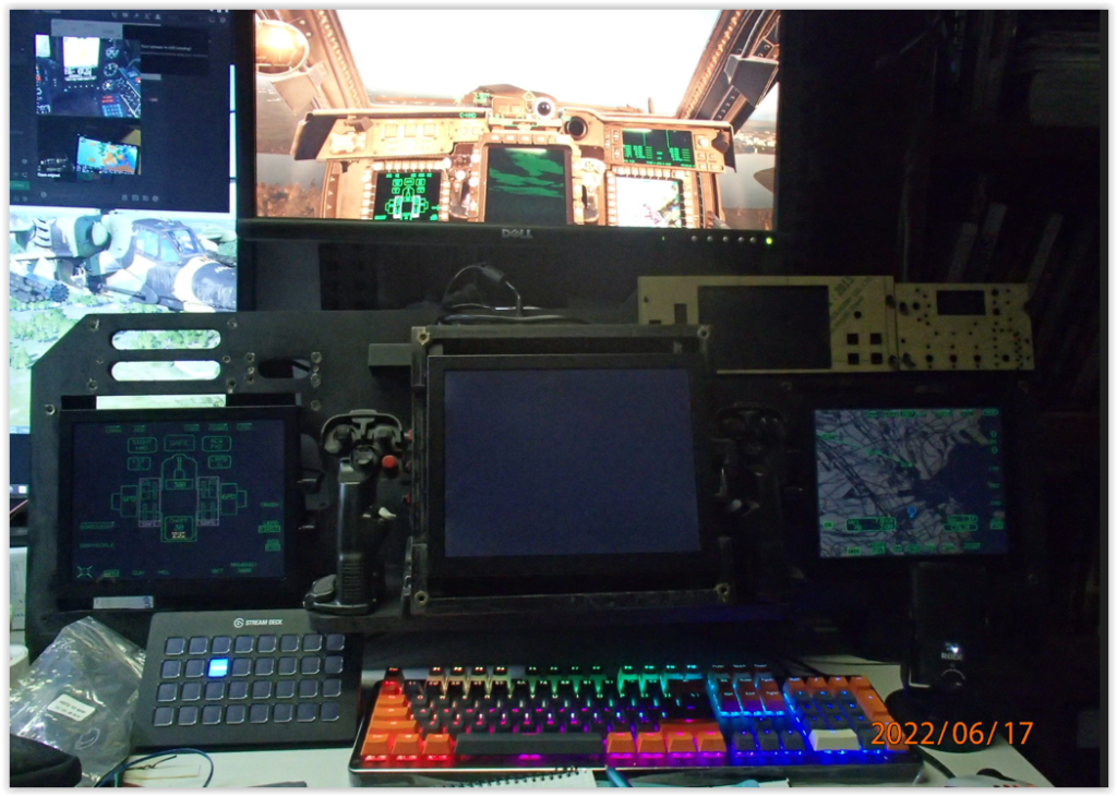
Now to mount it all up

upper dash & side consoles in place

The dash protursion is a big difference in asthetics, one of the driving factors for including this is the addition of angled mounts for the L & R MFDs to pan them back around to towards the CPG. this also made a big difference when sitting in front of the dash. Its amazing what a difference jsut a few degrees can make.

side console mounts

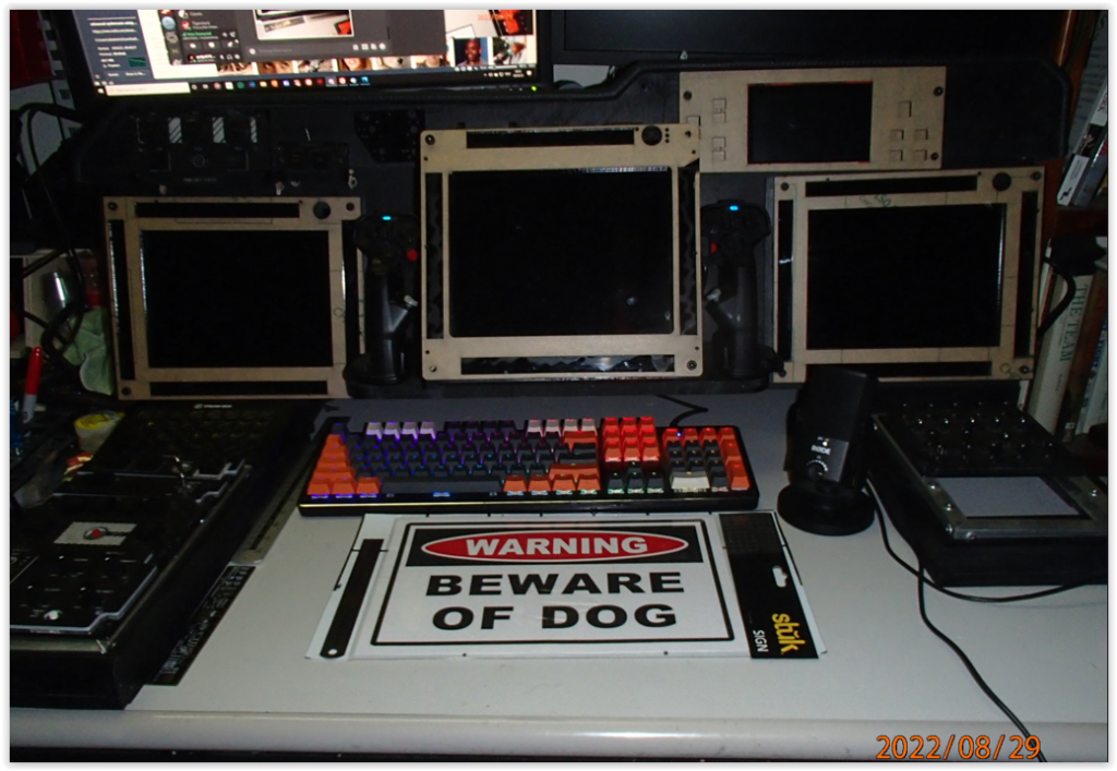
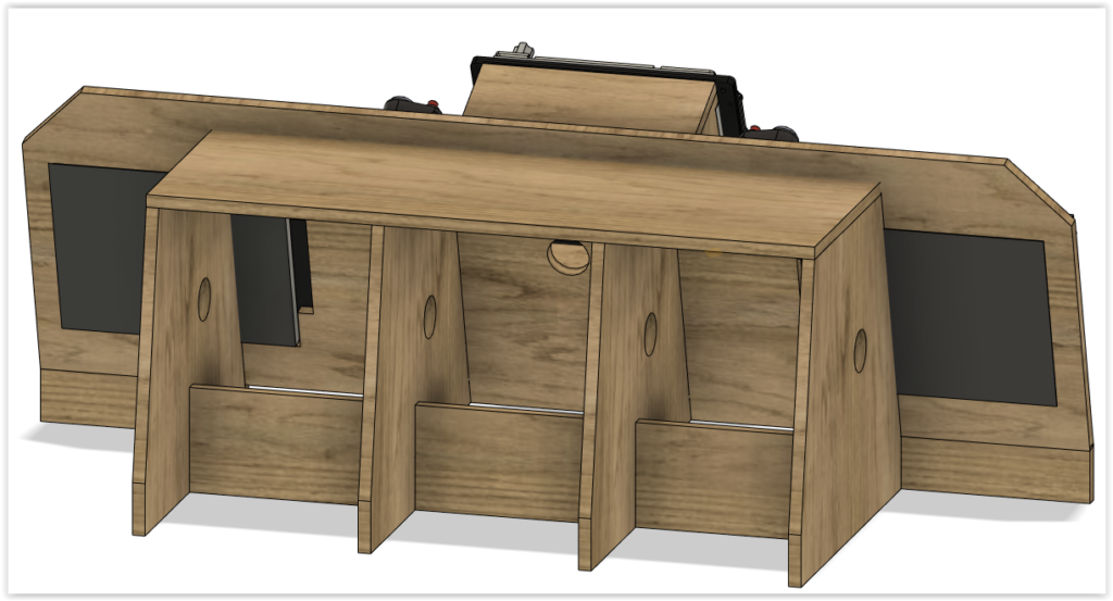
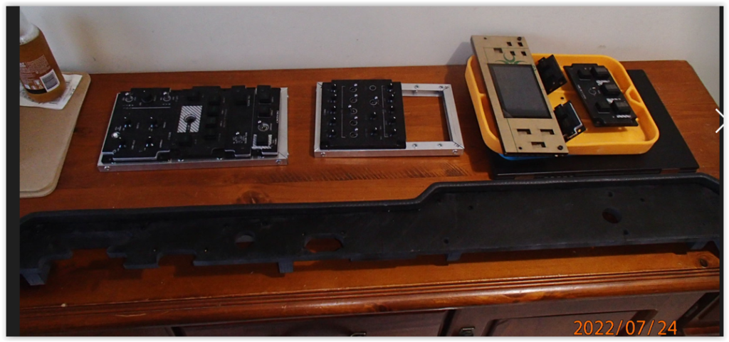
I finally got around to making side sections to seat the side console frame panels. lifting the switches up off the desktop & also allowing me to place the Streamdeck XL where the Keyboard Unit would go. At this point I am not going to make a KU until I am further along with the simpit design.

RH console

2 non-essential panels still missing from the RH console, they will be populated eventually.

LH console

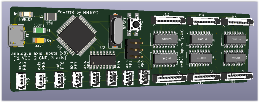
The RH console only just fits in the desktop depth, so I am unable to tilt the streamdeck / pseudo KU , but in this instance, it’s no biggy, the consoles now in place I can begin wiring them all up once I get my FreeJoy board prototypes.

FreeJoy prototype boards

Should be here this week touch wood. It will be great to finally get everything wired up.

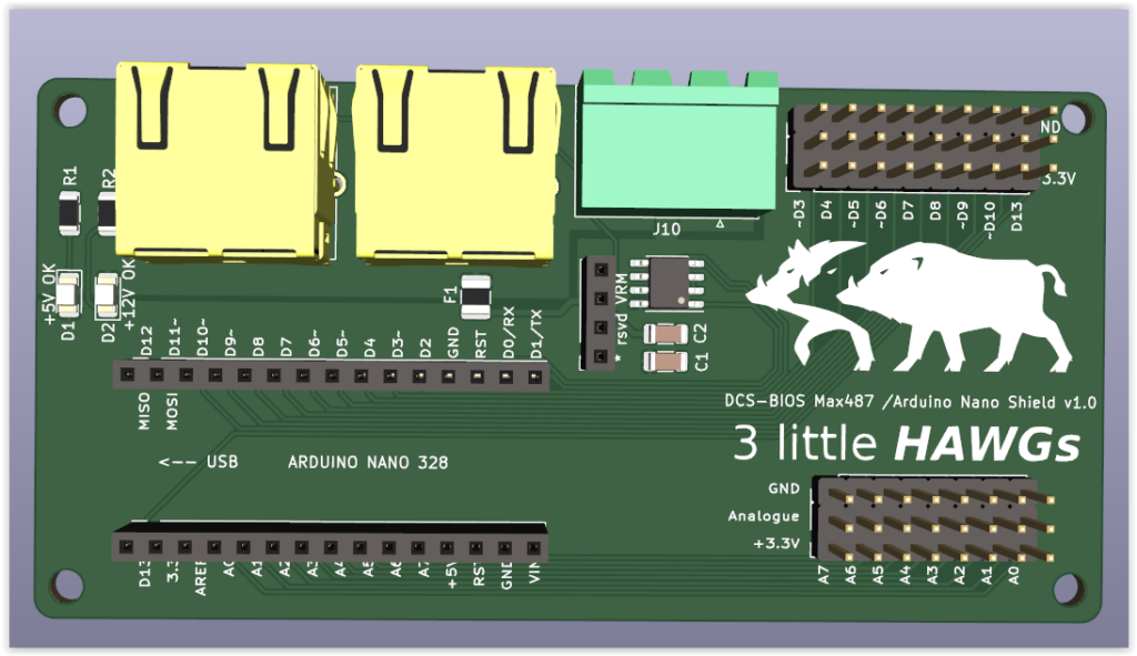
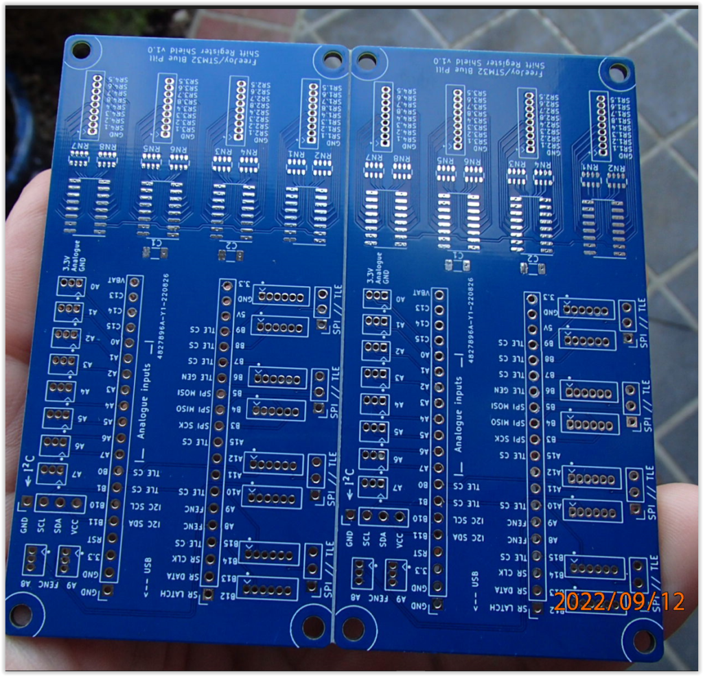
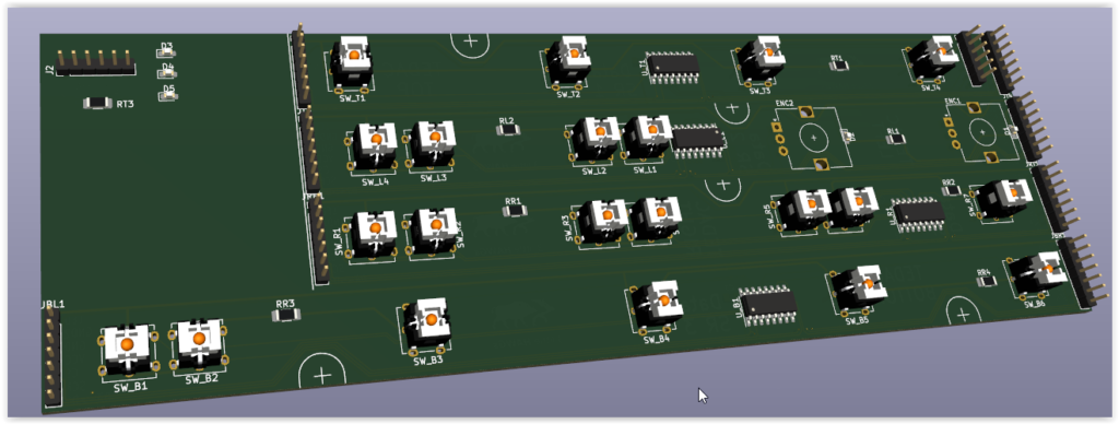
Freejoy PCBs arrived, unfortunately I do not have 100% of the required components, ironically specifically the smallest & hardest to get to ones, so any assembly preceding that would be counter-productive.

Freejoy PCB prototypes

another case of hurry up & wait in a post covid-19 world….

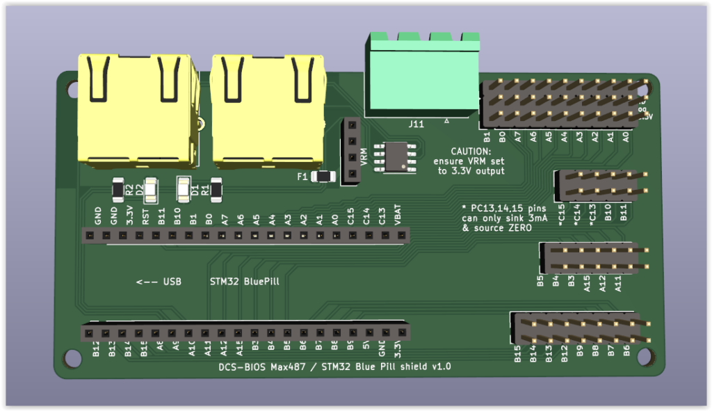
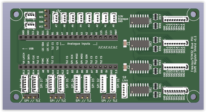
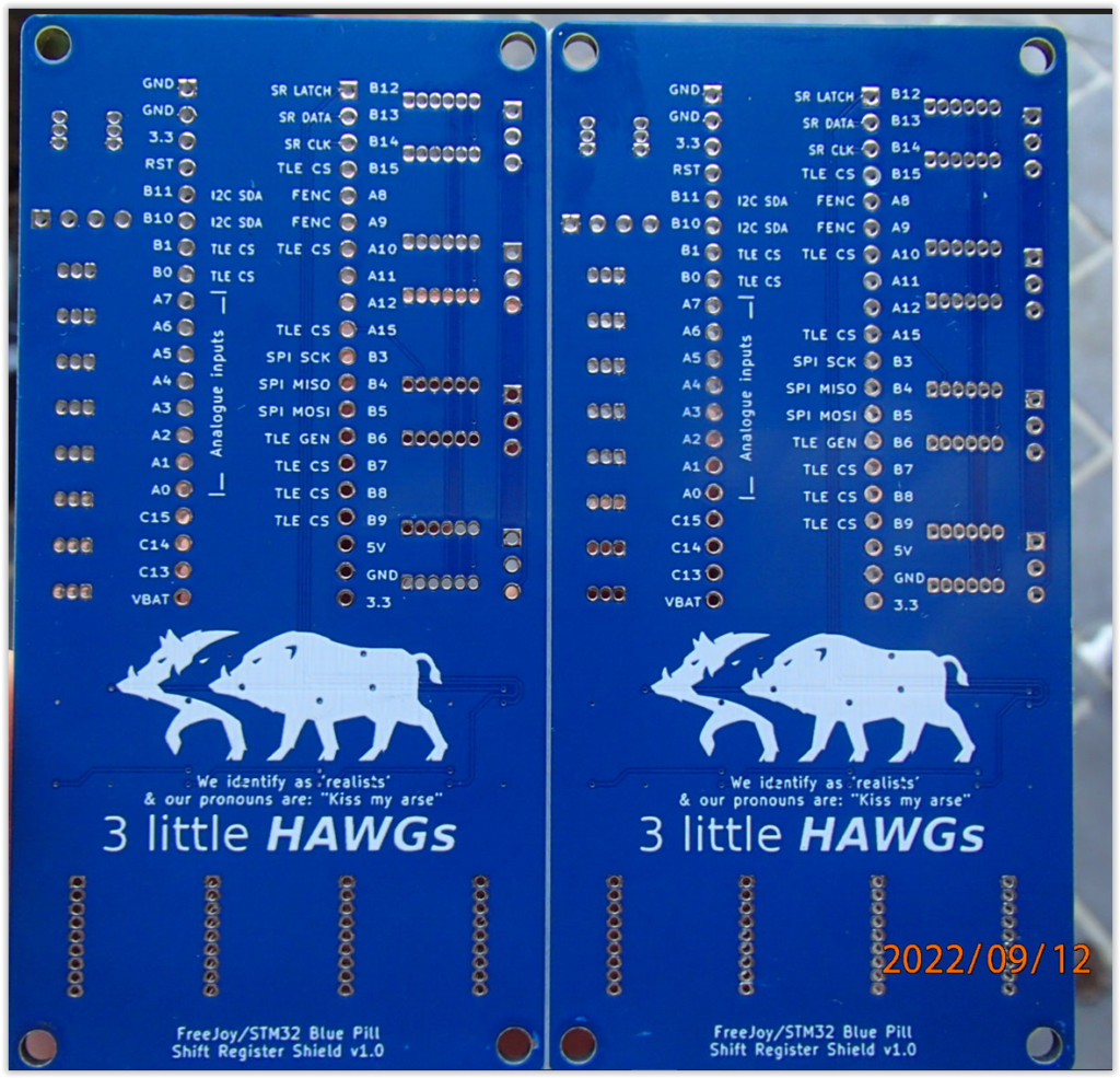
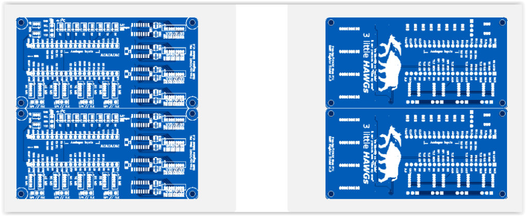
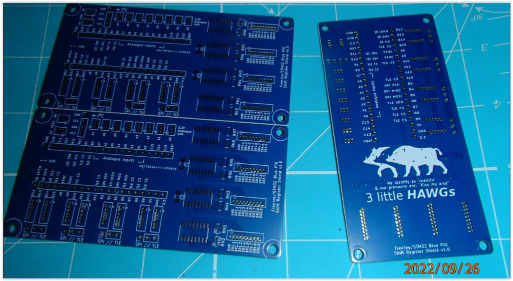
additional PCBs were also designed & sent off & have arrived as well.

each done in a different colour for no specific reason other than to test out how each one looks, in terms of aesthetics, silk screen readability, as well as ease of troubleshotting (trace following etc).

MFD PCB strips prototype

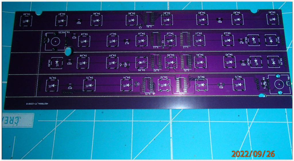
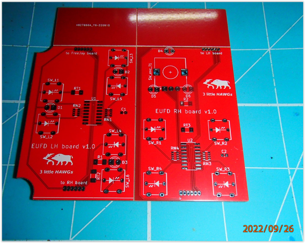
MFD strips in purple & EUFD in red…

EUFD (left & right) PCB prototypes

TEDAC MFD in white with black silkscreen….

A little bit of a hiatus as I’ve been waiting for rain to subside so that I could get my workbench out in order to continue work on the PCB strips; seperating them, sanding & cleaning up edges, & now soldering/assembly.

SMD components soldered

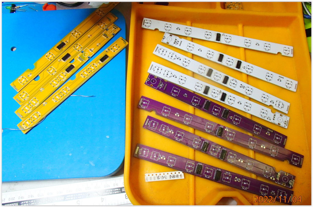
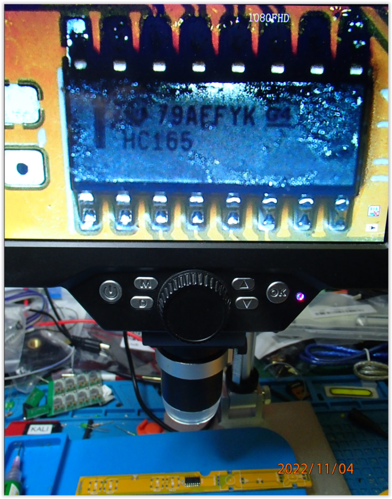
The initial hurdle was soldering the SMD resnets & Shift Registers to the strips… impossible (for me) without solder paste, heat gun, digital microscope & a very good iron

resnets through the microscope – not pretty – but working (uncleaned)

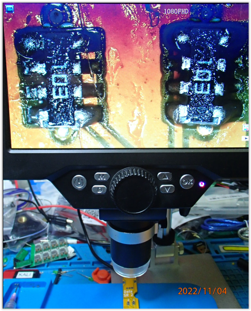
The Shift Registers are easy in comparison….

plenty of flux & drag soldering technique provides some decent results….

The MFDs are getting so close to being usable…. I can taste it.
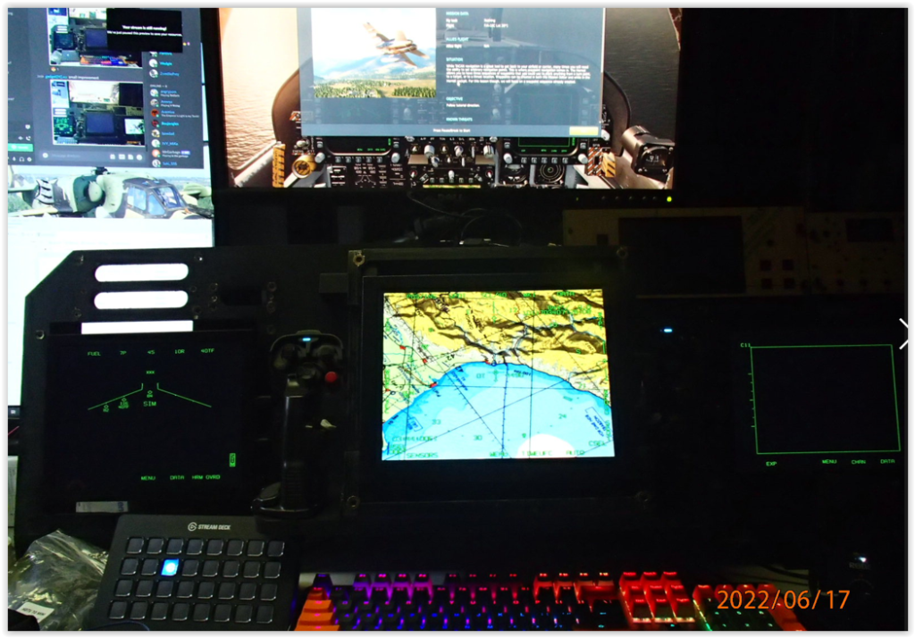
Left MFD strips with switchesRight MFD strips with switches
MFD with PCB strips

The left & Right MFD PCB strips are different colours for no real reason, other than I mistakenly ordered 2 sets of prototypes of the same board but in a different colour…. oh well, lemonade from lemons; I can now build 5 complete sets from the protoype boards, (if there is any demand for them).

TEDAC finally with switches!

I still have to put a few more SMD components on each strip, (a couple of resistors & the odd capacitor + the odd LED…then the connectors) but for the most part, these PCBs are just about done & ready to test….

& potentially let the ‘magic’ smoke out…..

AH-64D CPG dash for desktop use – design

Whilst still planning & designing the full tandem AH-64D simpit,

AH-64D full tandem simpit

I was sadly denying myself any flight time at all, so I decided to build an interim platform for short term use, whilst I also designed & fabricated all the flight panels.

Given the complexity of the TEDAC grips, I was pondering the viability of 2x (L&R) off the shelf grips that might prove a more readily accessible alternative to those who wanted the manual dexterity but were not in a position to manufacture their own grips.

tedac concept for off the shelf joystick grips

I threw around some ideas & settled on the concept above that allowed for grips to be mounted from below in order to use existing connections & mounting points. The crude system indicated the basic layout.

I had previously purchased a gladiator stick & a LH kosima SCG grip with the intention of making a’collective’ again using off the shelf components, but attention to detail bit me & I was unable to action it as intended & got caught up trying to design a replacement gimbal with a single axis travel etc.

tilted (single axis) joystick as collective

The plan was to mount the collective to the rear of a throttle so as to provide use of both fixed wing & rotary wing alternatives to sim pilots. Other projects & real life continued to interfere with this though & it was constantly put on the back-burner. Eventually I acquired a K-51 collective, so my requirement for this item decreased in priority significantly. Recently I saw posts where someone had done exactly what i was intending, though they utilised a base that had a metal gimbal which allowed for an axis to be locked out, which is perfect, no reinvention necessary.

To continue on with the full tandem pit was a test in futility, so to soothe my flying habit, I needed to come up with a solution that would allow me to fly as well as take advantage of each panel as they were created & mount them to prevent them from becoming damaged within the catastrophe that is my workspace.

The criteria was pretty simple

  • it needed to be wide enough to accomodate the 2x MFDs & TEDAC mounting points (1:1 scale wasn’t important)
  • it needed to provide a stow point for the keyboard when not required, but still allow for easy access.
  • the grips needed to mount from the bottom
  • there needed to be adequate dash real estate to accomodate other CPG panels.
  • the needed to be enough rigidity to support the monitor as it would consume the monitor stand normal space.

Firstly I had to establish the primary dimensions of height width & depth to ensure it would fit in the allocated desk space as well as accomodate all required panels. The finishing touches of top shelf & front trim would come once this was done.

the intial concept resulted in the following, very little changed from the initial concept to the final revision other than a few dimensions of the TADS ‘stem’

CPG Dash – Keyboard recess

the monitor shelf didn’t need to be the full length of the dash so it was made only wide enough to accommodate a standard keyboard

CPG dash-rear brace & monitor shelf

The rear of the keyboard recess has a vertical brace that locks in the monitor stand verticals, these also support the dash angle

The dash dimensions were tweeked a little to ensure all panels could be positioned without over crowding, again 1:1 wasn’t a concern in this instance, only functionality

CPG dash – panel placement

By utilising the joystick grips I also required the joystick base in order to get the button functionality, so after removing the gimbals from each & investigating the small PCBs within the base, I managed to map out safe areas to cut the bases into sections that would allow me to also use the majority of buttons/switches on each base, nice. Reducing these as much as possible & getting the angle right to provide optimum placement/accessibility whilst holding the grips. A little excess was allowed on the base panels so that I could drill new mounting holes if existing mounting holes/bosses, were not obvious.

cpg dash – stick grip & base button placement

I actually modelled the bases on the wrong sides, so the following images are incorrect, the gladiator base should be on the LH grip (oops)

cpg dash – stick grip & base button access Right grip

the 1st (LH) gladiator I acquired was the original gladiator (std not pro) along with the SCG & I didnt realise the grip did not seperate from the basetilise all the grip buttons so capitalising on the base encoders & buttons, it was also butchered to be placed hidden behind the TADS LH grip.

cpg dash – stick grip & base button access Left grip

the 2nd (RH) gladiator I acquired was when the new variants were release & the standard versions were reduced, so the base is different. Still require the components in the joystick base to utilise all the grip buttons so capitalising on the base encoders & buttons, it was also butchered to be placed hidden behind the TADS LH grip.

CPG full simpit

rather than creating a throttle quadrant I have decided to retain the warthog throttle & utilise it & its buttons to compliment the ah64 simpit, it can also double as a fixed wing throttle should I ever turn to the dark side.

DCS-BIOS framework via MAX487

Working on the solutions to provide the input controls as well as the lighting and output from DCS into our colleagues A-10C cockpit, we have come up with several ideas to provide a suitable, scalable & maintenance friendly solution to this, but hadn’t gotten very far when , once again we stumbled upon a very interesting post on the ED forums by Hansolo

https://forum.dcs.world/topic/208455-dcs-bios-over-rs485/

The quality & detail of this post is admirable, & follow up posts by forum members showing just how creative this sim community is, with several examples of custom PCB shields, which put us on the path of developing our own, once again based around the STM32 bluepill, to rationalise the different microcontroller cards we would be required to source.

DCS-BIOS slave boards

Being that we also already had several arduino nano boards, & the cost of producing a limited batch of these boards under prototype pricing is trivial amounts (<AUD$10 for 10 boards).

DCS-BIOS max487 – Arduino Nano shield board

The primary goal here was to utilise the STM32 bluepill so a similarly laid out shield board was also produced to suit it.

DCS-BIOS max 487 slave – STM32 bluepill shield board

Note that both of these DCS-BIOS slave shield boards have pin sockets for a Voltage Regulator Module sub-board to filter the 12v input, whether via the RJ45 or power connector & provide a more reliable 5V or 3.3V respectively.

DCS-BIOS master board

At the time of writing the DCS-BIOS master panel is only viable with an Arduino Mega 2560 card, due to the requirement of more than one TX/RX bus.

The Mega2560 is comparatively expensive option to the STM32 bluepill, which also has more than 1 TX/RX, so we are pursuing a solution where the STM32 bluepill can act as either the master or slave nodes in this framework, again attempting to rationalise MCU types & reducing overall variables & additional cost.

If the end result that the STM32 is not supported as the DCS-BIOS master node, then we will also need to design & produce a DCS-BIOS master shield to suita Mega 2560.

For the connection cables we selected RJ45 connectors as the leads are readily available & we have the tools to terminate custom cable lengths as required.

12V will need to be run to provide power to the LED backlighting throughout the cockpit, this can be run either through the RJ45 cable, or alternatively directly via the power connector on the shield board

MMJoy board to FreeJoy board journey

Initially the intention was to utilise a simple arduino clone pro-micro utilising an ATMEL32u4 microcontroller it would be able to be flashed with the MMJoy utility for ease of use.

However in order to get any decent fidelity sensitivity of analogue inputs, an Analogue to Digital Convertor to increase the bit resolution available.

MMjoy board initial concept

Whilst investigating this further the STM32 bluepill was discovered & the higher specs of this MCU was very attractive. Further investigation resulted in the discovery of the FreeJoy utility which worked on it.

This resulted in disbanding the MMJoy board & pursuing instead an STM32 solution, during the development of this project, covid-19 impacts to shortages in all industries saw prices of components going all over the place, it was actually cheaper to source complete bluepill boards than trying to aquire STM32 MCU chips as standalone items.

Freejoy STM32 bluepill shield board

Initial development of the FreeJoy board has therefore been done as a shield for a STM32 bluepill, but the intention is to provide a purpose built board including improved power management circuitry to avoid common issues with bluepills being inadvertantly bricked by newcomers.

STM32 Shield prototype

Having finalised the design for prototype / testing / proof of concept, the boards arrived & appear immaculate.

Freejoy Shield prototype – front

Some of the SMD components, specifically the Shift Registers are a larger available foot print to allow for easier hand-soldering, through hole components are also all hand soldered.

Freejoy Shield prototype – back

Now to solder the boards to a usable level & perform the testing.

Shortcomings of the STM32 bluepill

the STM32 is a much better microcontroller, however the readily available & inexpensive bluepill board is somewhat lacking & we have refined the design somewhat to add some sadly lacking safety features in the bluepill which can & often results in bricked boards. (One of our friends destroyed 3 seperate boards in one sitting).

To overcome this we have decided to move away from the shield design board, though that might still be made available if an indicated demand exists, in favour of a custom built board with refined safety features & eliminates the requirement of also purchasing a bluepill board.

purpose built Freejoy board design

These customised purpose built boards will be shipped with the current version of FreeJoy configurator installed ready for use. Configuration files can be accessed by a download & applied, or created & manually customised to personal preference.

3 little HAWGs build logs

Welcome to the rabbithole that is our design history

In order to provide more background into the amount of time & effort required to produce our products, some of the design goals & thought processes to eliminate options & rationalise features, we felt it prudent to provide a platform like this to give some detail.

It is easy to poo-poo a products value, whilst still demanding simplicity & usability (plug & play) capabilities, however the more you design the features into something to be simpler to use, the more complicated it can become. The more time spent on research & development, the higher the value for the end product in order to recoup the investment of time, money & effort in order to bring something to production.

If you’re not happy with that reality, then by all means attempt to do the same thing yourself, we are all content to not have our time wasted by some penny pincher who doesn’t understand the value of someone technically proficient in a field they know little to nothing about. We have all had to deal with our own variations of these types; people / project / general manglement. We are very sastisfied to not have to put up with their oxygen thieving rhetoric in time-wasting meetings to discuss the latest buzzwords they might have picked up in their latest middle manglement sessions.

It is impossible to cater for every scenario, customer request, exception, variable & most troubling of all….. you cannot code for stupid.

There will always be one individual that cannot grasp what you might have assumed is common knowledge;

helpdesk: realisation...."*sigh*....Do you still have the box it came in....?"
client" "Yes"
helpdesk: "pack it up, take it back"
client" "OK, but what do i tell them?"
helpdesk: "tell them you're too f@#king stupid to own a computer" - click

(if only we all had the opportunity to experience that much job satisfaction…. )

That said, for all those I’ve offended; so what – nothing happens!

(you are the only person who can allow yourself to be offended… )

We are all old school, politically incorrect, socially inept, non-woke, realists, who believe in scientific facts, specifically (& not limited to);

  • the world is round
  • there are 2 biological genders (men have penis & testicles, women have vagina, uterus & ovaries)
  • you can live/call yourself whatever you want, more power to you…. just don’t try to FORCE us to.
  • ALL lives matter, you idiots. I speak 2 languages, am in a mixed race marriage & did 2 operational tours with the united nations – so don’t call me a racist simply because I am white.
  • politicians, lawyers, used car salesman real estate agents & managers are all equally worthless
  • goggle, face-ache, micro$haft, scamsung , shamazon, crapple, Tesla & the CCP are all equally evil
  • a sentence should never start with “best way is…” or “just….”
  • guns don’t kill people – people kill people
  • J.R.R. Tolkiens works are NOT up for interpretation; read the lore details – its ALL there
  • the F-35 is a multi-billion $ homer-mobile
  • any ‘manager’ who says, “how hard can it be…? JUST click on setup.exe” should be beaten senseless with the nearest blunt heavy object.
  • the world is full of ask-holes (a person who constantly asks for your advice, yet ALWAYS does the complete opposite of what you told them to do)
  • if you don’t like our sense of humour, feel free to go somewhere else (get out of my grid square & stop thieving my oxygen)